
KeithB
Resident Half Fast Machinist
Our shop has a Haas TL1 CNC lathe, and it's a fine piece of equipment. When I bought it there were two options availablen for tooling - a four position automated tool holder, or a dovetail wedge type toolholder. I selected the manual option, it allows as many as 99 tools to be used and is cheaper and more versatile in my opinion. There are two shortcomings to this. The toolholder blocks are heavy and having to handle numerous tools can be wearying. And while most machining operations can be performed pretty well, drilling and tapping can be a little iffy.
Many of the parts we make are less than 2" diameter and just a few inches long. The TL1 has a 16" swing and 8 full inches of cross slide travel. After a little thought I came up with a new toolholder setup that accomplishes the following goals:
1. Minimize tool changes.
2. Be able to drill holes using the carriage instead of the tailstock.
3. Be able to tap holes under power.
This photo shows the TL1 as it was delivered. You can see the cross slide has no compound rest (it's CNC and doesn't need one). The wedge type toolholder attaches to the cross slide by bolting it to a mounting block with a T-slot. The block is about 3.5" high, 4" thick, and 5.5" long and attaches to the cross slide with two 5/8-11 socket head cap screws. There are 9 tapped holes in the cross slide so the standard tool block can be attached in several places and orientations. I planned to take advantage of these extra holes.

After doing some research on available tooling I found a place that sells collet holders on round bars. Since I already use ER16 and ER32 collets on the CNC mill it would be a low cost way to hold drills and taps - yes, they make collets that are designed specifically to hold taps without slipping.
After taking measurements and aided with the Haas documentation I was able to design a toolholder setup that would replace the standard mounting block with a 12" long one, allowing a series of different tool holders to be bolted in place. Here is a screen shot of the basic components (not all shown).

Just to be sure I wasn't missing something I decided to make a full size 3D model of the basic parts. Since I don't have rapid prototyper I did it the way I learned to do it 45 years ago in high school when I took pencil and paper drafting. I made "sheet metal layouts" of the surfaces, printed out the parts at full size, cut them out, folded them and taped them together. It's sloppy, my teacher then would have scolded me, but it was good enough to take out to the shop and put on the cross slide end to end with the existing block. This enabled me to jog the carriage and slide around in real space around demo parts to check for clearances and potential problems.

Once I was sure that the idea was viable we set about making the actual pieces. It was all rather straight forward machine work. The base mounting block was made from three pieces, I didn't want to buy a special T-slot cutter. The base and top bars align with three 1/4" pins each. The photo shown here shows the assembled mounting block in the CNC mill vise, the top and inside edges have just been machined. A blank toolholder block and T-slot nut is there to test the width of the slot.

After machining the base it was mounted on the cross slide and indicated in straight . In order to make the holes in the toolholder blocks concentric with the spindle rotation we used the lathe opposite the way it normally is used. We bolted the blocks in place and ran the tools in the lathe chuck. To start out we mounted a 1.5" OD adapter w/a #4 Morse taper socket in the chuck, then we used the chuck to hold a needle point shaft. We used this to find the center of the block and recorded that offset. Then we switched to a center drill, next a 3/8" drill, followed by a 7/8" drill. For the toolholders with 1" and 1.25" holes we stopped there and switched to the boring bar setup. The block shown has a 1.5" ID finished hole, so the chuck was removed and a three flute 1-1/4" core drill with a #4 Morse shank was used to enlarge the hole.


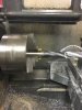
In order to finish the holes a homemade boring bar was made from a piece of 3/4" cold rolled rod. A cross hole was drilled and then broached to 1/4" square and a piece of HSS tool blank was used, The tailstock center supports the end of the bar and the carriage travel provides the feed. The three shots below show a tool holder that will end up with a 1" hole. The hole was bored to within about 0.020 of finished size and a 1" machine reamer was run through the bore.
Many of the parts we make are less than 2" diameter and just a few inches long. The TL1 has a 16" swing and 8 full inches of cross slide travel. After a little thought I came up with a new toolholder setup that accomplishes the following goals:
1. Minimize tool changes.
2. Be able to drill holes using the carriage instead of the tailstock.
3. Be able to tap holes under power.
This photo shows the TL1 as it was delivered. You can see the cross slide has no compound rest (it's CNC and doesn't need one). The wedge type toolholder attaches to the cross slide by bolting it to a mounting block with a T-slot. The block is about 3.5" high, 4" thick, and 5.5" long and attaches to the cross slide with two 5/8-11 socket head cap screws. There are 9 tapped holes in the cross slide so the standard tool block can be attached in several places and orientations. I planned to take advantage of these extra holes.
After doing some research on available tooling I found a place that sells collet holders on round bars. Since I already use ER16 and ER32 collets on the CNC mill it would be a low cost way to hold drills and taps - yes, they make collets that are designed specifically to hold taps without slipping.
After taking measurements and aided with the Haas documentation I was able to design a toolholder setup that would replace the standard mounting block with a 12" long one, allowing a series of different tool holders to be bolted in place. Here is a screen shot of the basic components (not all shown).
Just to be sure I wasn't missing something I decided to make a full size 3D model of the basic parts. Since I don't have rapid prototyper I did it the way I learned to do it 45 years ago in high school when I took pencil and paper drafting. I made "sheet metal layouts" of the surfaces, printed out the parts at full size, cut them out, folded them and taped them together. It's sloppy, my teacher then would have scolded me, but it was good enough to take out to the shop and put on the cross slide end to end with the existing block. This enabled me to jog the carriage and slide around in real space around demo parts to check for clearances and potential problems.
Once I was sure that the idea was viable we set about making the actual pieces. It was all rather straight forward machine work. The base mounting block was made from three pieces, I didn't want to buy a special T-slot cutter. The base and top bars align with three 1/4" pins each. The photo shown here shows the assembled mounting block in the CNC mill vise, the top and inside edges have just been machined. A blank toolholder block and T-slot nut is there to test the width of the slot.
After machining the base it was mounted on the cross slide and indicated in straight . In order to make the holes in the toolholder blocks concentric with the spindle rotation we used the lathe opposite the way it normally is used. We bolted the blocks in place and ran the tools in the lathe chuck. To start out we mounted a 1.5" OD adapter w/a #4 Morse taper socket in the chuck, then we used the chuck to hold a needle point shaft. We used this to find the center of the block and recorded that offset. Then we switched to a center drill, next a 3/8" drill, followed by a 7/8" drill. For the toolholders with 1" and 1.25" holes we stopped there and switched to the boring bar setup. The block shown has a 1.5" ID finished hole, so the chuck was removed and a three flute 1-1/4" core drill with a #4 Morse shank was used to enlarge the hole.
In order to finish the holes a homemade boring bar was made from a piece of 3/4" cold rolled rod. A cross hole was drilled and then broached to 1/4" square and a piece of HSS tool blank was used, The tailstock center supports the end of the bar and the carriage travel provides the feed. The three shots below show a tool holder that will end up with a 1" hole. The hole was bored to within about 0.020 of finished size and a 1" machine reamer was run through the bore.


 Couple of bearings, a shaft with

