
You are using an out of date browser. It may not display this or other websites correctly.
You should upgrade or use an alternative browser.
You should upgrade or use an alternative browser.
Titanium Silencer on a Form 1
- Thread starter L1A1Rocker
- Start date
L1A1Rocker
Active Member
Thank you folks for the comments. It's much appreciated.
Well, while this project was going on, Ian happened along one day. He was asking me what the various parts weighed and how much the tube weighed, and what the total would weigh, he even asked me how much the muzzle brake weighed, and he. . . seemed to have weight on the brain. And so I asked what was what.
He started telling me about his Form 1 project he had in the hopper, he even showed me a titanium muzzle brake he brought over. So I guess the gauntlet had been thrown down. Time to shed some weight.
The most obvious was the K-baffles. K's, by their nature weigh a lot. If you recall these Ks were in process before I had finalized the design. Going with that notch design left a LOT of meat on the plate. So they had to go on a diet.
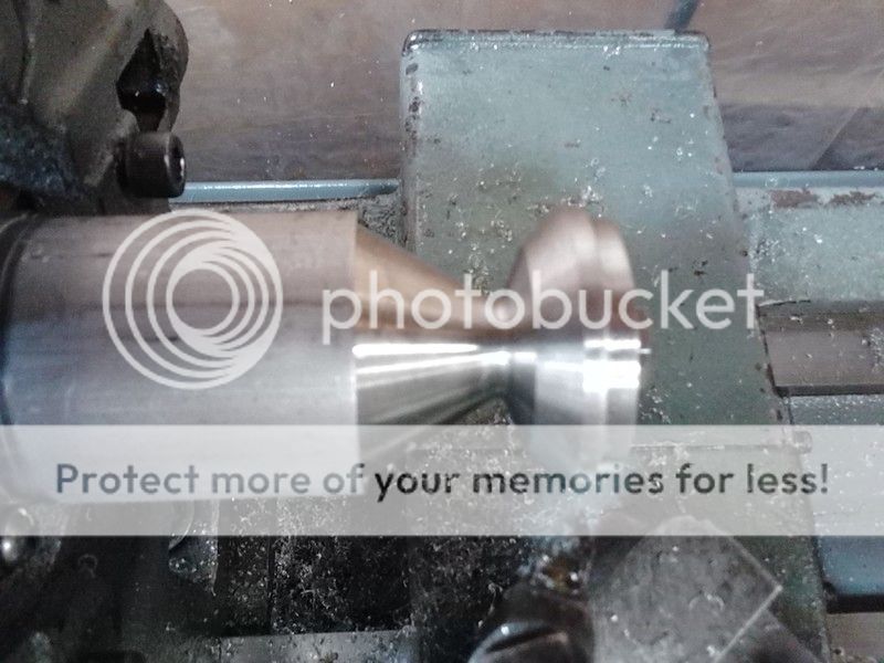
Soooo, time to make another mandrel, LOL. I started by turning down some aluminum barstock to a 60* angle and threading the end. Then I tuned out some backing plates. The idea was to sandwich the K baffle on the end so that I could turn off the excess material.
That didn't work worth a darn! I absolutely could NOT get the baffle tightened down and running "true". I needed a square flat surface. Back to the drawing board.

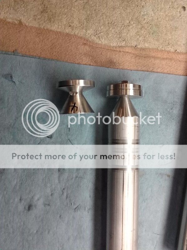
That was MUCH better. Now I just turned off some material at the same angle as the inside. The idea was to make sure everything was no thinner than .08 inch.
And here's a side by side to show how much was taken off.
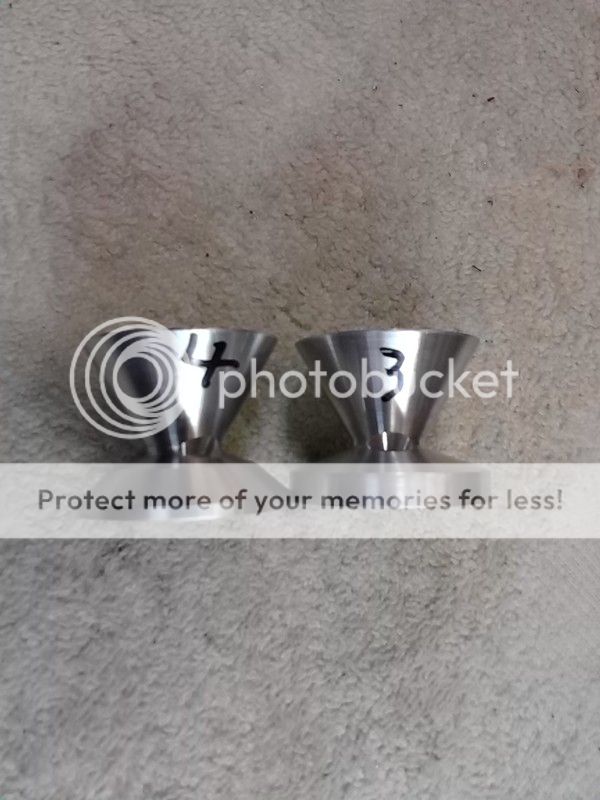
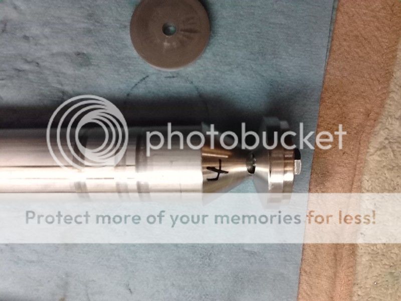
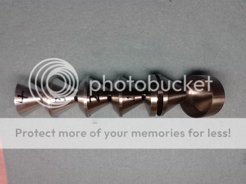
I decided to leave the first K-baffle alone for the sake of strength. Here's a lineup off all the baffles. 2 cone baffles and 4 K-baffles.
Now on to something that had me rather befuddled. My design had the front endcap with a cone of it's own on the inside. Most silencers end with just a flat endcap, or a profile similar to the plate of the K-baffle. I wanted something better and the cone seemed good to me. BUT, it left a large section where the bullet would be passing down with walls all the way around it. That could generate a "pre cursor pulse" and had me concerned. I kinda put it out of my mind ans was just going to "go with it". And I probably would have if not for the prodding from Ian.
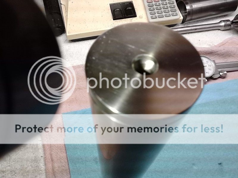
Here's a refresher on what the endcap looks like:
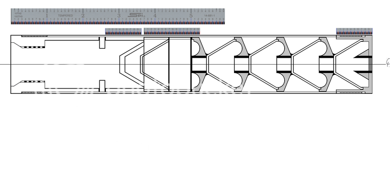
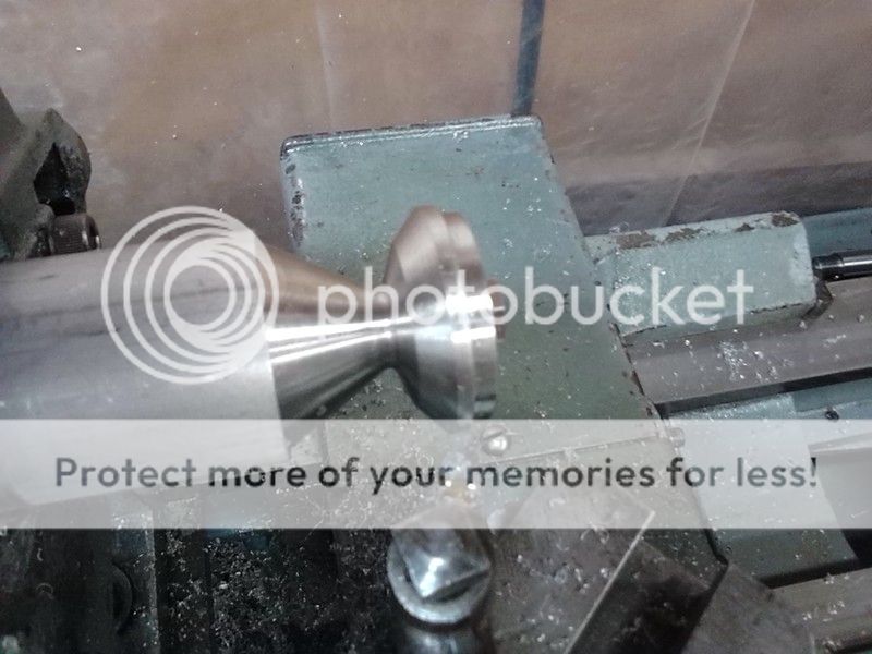
I wanted to carve out some of the innards of that last cone, essentially making another "baffle" inside the endcap.
That would require a very special tool. Back to the grinder. . .


This made for a VERY tight fit.

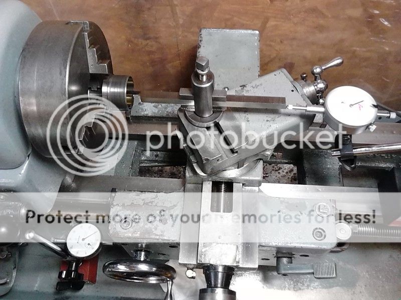
Ok, the tool was made. Now how do I do this without being able to see. The normal operation when carving an angle is to lock the carriage down, work the compound manually to cut, and move the cross slide a few thousands making your cut a bit deeper as you go. Well, because I was working inside a hole, I could not move my cross slide, I'd have to move the carriage. The problem with that is that he carriage has no measuring dial on it, it wasn't meant to work that way. My solution was to mount a dial indicator on the drip tray indicating on the front of the carriage.
Now my problem was to know when to stop my compound advance as I cut material away. I couldn't use the dials on the compound because the amount fed in would change everytime i moved the carriage down. The solution was a dial indicator mounted the the carriage and indicating on the back of the cutting tool.
I'm sure the above was really clear as mud so let me try to explain a bit better. I have to put this cutting tool down a hole, and at some point I have to start advancing the cutting tool into the side of the hole at a 60* angle. I have to stop advancing the tool at the same point every time so I end up with a nice shelf at the end. I cannot see any of this cutting and have to rely on a dial indicator on the front, and a dial indicator at the back to tell me where the tool is inside that hole. Simple right?
Continued. . .
Well, while this project was going on, Ian happened along one day. He was asking me what the various parts weighed and how much the tube weighed, and what the total would weigh, he even asked me how much the muzzle brake weighed, and he. . . seemed to have weight on the brain. And so I asked what was what.
He started telling me about his Form 1 project he had in the hopper, he even showed me a titanium muzzle brake he brought over. So I guess the gauntlet had been thrown down.
Time to shed some weight. The most obvious was the K-baffles. K's, by their nature weigh a lot. If you recall these Ks were in process before I had finalized the design. Going with that notch design left a LOT of meat on the plate. So they had to go on a diet.
Soooo, time to make another mandrel, LOL. I started by turning down some aluminum barstock to a 60* angle and threading the end. Then I tuned out some backing plates. The idea was to sandwich the K baffle on the end so that I could turn off the excess material.


That didn't work worth a darn! I absolutely could NOT get the baffle tightened down and running "true". I needed a square flat surface. Back to the drawing board.


That was MUCH better. Now I just turned off some material at the same angle as the inside. The idea was to make sure everything was no thinner than .08 inch.


And here's a side by side to show how much was taken off.

I decided to leave the first K-baffle alone for the sake of strength. Here's a lineup off all the baffles. 2 cone baffles and 4 K-baffles.

Now on to something that had me rather befuddled. My design had the front endcap with a cone of it's own on the inside. Most silencers end with just a flat endcap, or a profile similar to the plate of the K-baffle. I wanted something better and the cone seemed good to me. BUT, it left a large section where the bullet would be passing down with walls all the way around it. That could generate a "pre cursor pulse" and had me concerned. I kinda put it out of my mind ans was just going to "go with it". And I probably would have if not for the prodding from Ian.
Here's a refresher on what the endcap looks like:
I wanted to carve out some of the innards of that last cone, essentially making another "baffle" inside the endcap.
That would require a very special tool. Back to the grinder. . .


This made for a VERY tight fit.

Ok, the tool was made. Now how do I do this without being able to see. The normal operation when carving an angle is to lock the carriage down, work the compound manually to cut, and move the cross slide a few thousands making your cut a bit deeper as you go. Well, because I was working inside a hole, I could not move my cross slide, I'd have to move the carriage. The problem with that is that he carriage has no measuring dial on it, it wasn't meant to work that way. My solution was to mount a dial indicator on the drip tray indicating on the front of the carriage.
Now my problem was to know when to stop my compound advance as I cut material away. I couldn't use the dials on the compound because the amount fed in would change everytime i moved the carriage down. The solution was a dial indicator mounted the the carriage and indicating on the back of the cutting tool.
I'm sure the above was really clear as mud so let me try to explain a bit better. I have to put this cutting tool down a hole, and at some point I have to start advancing the cutting tool into the side of the hole at a 60* angle. I have to stop advancing the tool at the same point every time so I end up with a nice shelf at the end. I cannot see any of this cutting and have to rely on a dial indicator on the front, and a dial indicator at the back to tell me where the tool is inside that hole. Simple right?
Continued. . .
Last edited:
L1A1Rocker
Active Member
continuation. . .
Here's what the set up looked like:

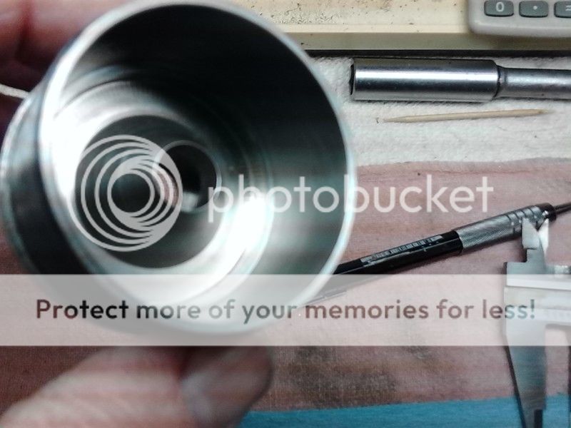
The procedure was to lock down the carriage, advance the cutting tool with the compound, return the compound to zero, unlock the carriage, move carriage down a few thousands, lock carriage down, and repeat many many times. It took a long time, but it worked. I wound up with an endcap with a very nice hollowed out cone baffle in it.
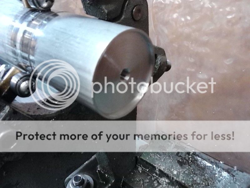
Here's a pic "in process"
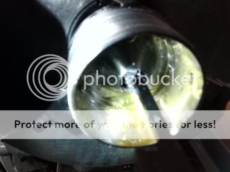
Hopefully you can see in there to see the hollowed out portion:
Well, we are getting close to being done. Just a bit of finishing touches to do. Please stay tuned.
Here's what the set up looked like:


The procedure was to lock down the carriage, advance the cutting tool with the compound, return the compound to zero, unlock the carriage, move carriage down a few thousands, lock carriage down, and repeat many many times. It took a long time, but it worked. I wound up with an endcap with a very nice hollowed out cone baffle in it.
Here's a pic "in process"

Hopefully you can see in there to see the hollowed out portion:


Well, we are getting close to being done. Just a bit of finishing touches to do. Please stay tuned.
Last edited:
smokeywolf
Well-Known Member
Yep, 2-flute endmills are at best, problematic for the stainless/titanium/space age metals. I prefer 3-flute when I can get them (and afford them). 2-flute can be a little flimsy and 4-flute often don't have sufficient chip clearance to evacuate chips from a hole or channel. A 3-flute with a 37 degree helix is a jack of all trades end mill.
I like the looks of you little horizontal mill. I had an Elgin horizontal about that size in the studio machine shop. Kept it set up to cut keyways and splines in shafting.
Also like the looks of what appears to be a precision grinding vise that you've got bolted to your angle plate.
For deep hole drilling or drilling with an endmill, if you have a fair sized air compressor and tank it may benefit you to look into a mister. You probably already know what I'm referring to, but for others not familiar with machining, it's a nozzle unit that sprays a precisely aim-able fine mist of coolant/cutting oil which you can direct right at the cutting edge of your lathe bit, endmill, drill, etc. While providing just enough lubricant to the cutting operation, they carry heat away better than anything other than "flood coolant".
Very anxious to see the finished article and read of the results of all your work.
L1A1Rocker
Active Member
Yep, 2-flute endmills are at best, problematic for the stainless/titanium/space age metals. I prefer 3-flute when I can get them (and afford them). 2-flute can be a little flimsy and 4-flute often don't have sufficient chip clearance to evacuate chips from a hole or channel. A 3-flute with a 37 degree helix is a jack of all trades end mill.
I like the looks of you little horizontal mill. I had an Elgin horizontal about that size in the studio machine shop. Kept it set up to cut keyways and splines in shafting.
Also like the looks of what appears to be a precision grinding vise that you've got bolted to your angle plate.
For deep hole drilling or drilling with an endmill, if you have a fair sized air compressor and tank it may benefit you to look into a mister. You probably already know what I'm referring to, but for others not familiar with machining, it's a nozzle unit that sprays a precisely aim-able fine mist of coolant/cutting oil which you can direct right at the cutting edge of your lathe bit, endmill, drill, etc. While providing just enough lubricant to the cutting operation, they carry heat away better than anything other than "flood coolant".
Very anxious to see the finished article and read of the results of all your work.
Doh!!! I've GOT one of those midget sprayers too. Why didn't I think of using it??? I wish I had the vice that went with the mill but that little vice seems to work well. It actually came mounted on my Atlas Shaper. (no, the shaper also does not have the vice that came with it LOL)
Smokey, I think you were typing as I was posting the next post. I'd really like your input on the carving out of the end cap. Specifically if you have any suggestions for doing it differently/better.
Thank you for your comments and input!
smokeywolf
Well-Known Member
You guessed right. I was typing as you posted #104. Also getting called away every 10 minutes.
I tend to be a bit obsessive when it comes to rigidity in a setup. For that reason I might have leaned toward leaving more meat on my boring bar, if indeed clearances would allow. Really beautiful grinding job though.
For most of my first 10 years as a machinist, none of the mills and lathes I used had DRO. I learned early to rely on dial travel indicators to measure cutter movements and locate part features. I've used setups resembling yours more times than I can count.
One thing comes to mind with your mill drilling. When drilling with an endmill, usually best to center drill, drill undersize and short of finish depth with a screw-machine length drill (No screw-machine length drill? grind one from a jobber length.), then finish with the end mill. This solves the problem of the flimsy 2-flute endmill and the lack of chip clearance of the 4-flute endmill.
L1A1Rocker
Active Member
You guessed right. I was typing as you posted #104. Also getting called away every 10 minutes.
I tend to be a bit obsessive when it comes to rigidity in a setup. For that reason I might have leaned toward leaving more meat on my boring bar, if indeed clearances would allow. Really beautiful grinding job though.
I'm with you on that. I made it as narrow as I thought I could get away with, and took very shallow cuts. The narrower I went with the bar, the deeper I could get into the "hollow". It was a trade off.
For most of my first 10 years as a machinist, none of the mills and lathes I used had DRO. I learned early to rely on dial travel indicators to measure cutter movements and locate part features. I've used setups resembling yours more times than I can count.
I'm assuming I got the set up close to right? That was my first time and I'm embarrassed to say that I thought long and hard on how to set that up. If not for Ian's prodding I might not have attempted it.
One thing comes to mind with your mill drilling. When drilling with an endmill, usually best to center drill, drill undersize and short of finish depth with a screw-machine length drill (No screw-machine length drill? grind one from a jobber length.), then finish with the end mill. This solves the problem of the flimsy 2-flute endmill and the lack of chip clearance of the 4-flute endmill.
I've been wanting some machine length drills - they're on my wish list. For some reason though, I didn't think to just grind a jobber down. Thanks for that advice, it's much appreciated.
smokeywolf
Well-Known Member
One thing about cutting a jobber length drill down and regrinding the tip; you've got to split the point or thin the web, one or the other. With a small drill, that takes a finely dressed wheel and a steady hand. Judging by the job you did on that boring bar, you have both.
L1A1Rocker
Active Member
One thing about cutting a jobber length drill down and regrinding the tip; you've got to split the point or thin the web, one or the other. With a small drill, that takes a finely dressed wheel and a steady hand. Judging by the job you did on that boring bar, you have both.
Thanks for that tip. I'm sure I'll be doing that at some point in the future.
L1A1Rocker
Active Member
Did you grind that from HSS? If so, that is likely the nicest looking tool ground like that I have even seen.
Beautiful work on the too.ng, setup, and the supressor. You are far better at this than you realize.
Yes, that's HSS. I would have preferred to use HSS +10% Co. But I used my last blank of that making the trepanning tool to carve out the EndCap. Thanks but I have to give credit to the tools. I rough grind on a bench grinder then move over to a one inch belt sander with a rough grit to shape it. Then I put a fine belt on to finish out the shape. Then I move over to a diamond wheel to sharpen. IIRC, I think I posted how I rebuilt a cheep harbor freight unit so that I could run the diamond wheel. Anyhow, thank you for the kind words.
L1A1Rocker
Active Member
So what's next after you get the suppressor done?
What other projects do you have planned.
I really enjoy watching your progress on this.
I hope it sounds as good as it looks.
Most immediately will be a self contained recoil system for my AR's. Something to get rid of the "thoungggg" spring noise that will drive you crazy when a silencer is attached to an AR. You never notice how bad it is until you run a silencer. I've got one prototype done that I've halfway played with. Truth is I like to tinker more than shoot. Ian's had it a while and found a few problems that I'll try to iron out, then I crank a few of those out.
After that, I'll try to put the silencer attachment system through some stress to see how it holds up. It the 60* shoulder works I'll keep it as a standard for my other rifles. If not, I'll change that angle and try again.
I'm sitting on several approved Form 1s that I haven't actually started on. One that's got my interest is an intagrall build on a Ruger 96/44. I've already got the barrel blank to make a fast twist barrel to shoot the heavy sub-sonic pills.
Of course I've got a Form 1 approved for another 30cal can, that 44 I mentioned, and a 45 that I plan on making a booster for to run on one of my Para Ordance P-14s. I figure I've got several years worth of projects lined up. . . .
F
freebullet
Guest
Fantastic work! Your machining is impressive.
I didn't see the weight listed. I was quite curious about that also, curious if you had any noise reduction goal/expectation with the design?
On the ar spring noise have you tried good synthetic oil or a light weight grease? Only reason I ask is it made a significant difference for me. I tried several methods to quiet a 308 buffer spring. With the long a2 stock it seemed excessively loud even without a suppressor. Coating the spring with oil and running a light grease coated patch down the tube seemed to help some. I certainly look forward to your progess posts and any other builds you share with us.